


While most modern legged robots rely on rotary actuators, particularly Quasi Direct Drives (QDDs), Tesla has taken a noticeably different path with Optimus choosing Linear actuators instead. At first glance, this decision seems counterintuitive, especially given how popular QDDs have become in legged robotics.
However, when viewed through the lens of system-level dynamics, inertia management, and energy efficiency, Tesla’s approach begins to make a lot of sense.
Why QDD Became the Default Choice?
QDD actuators gained popularity for good reasons. They offer:
- Back-drivability
- Compact motor and gearbox integration
- Low reflected inertia at a single joint
- Direct torque control
For single-DoF joints, QDDs perform exceptionally well. But humanoid legs are not single-joint systems they are multi-DoF mechanisms, and this is where the limitations begin to appear.
The Drawbacks of Using QDDs in Leg Mechanisms
When QDDs are deployed across multiple joints in a leg:
- Actuator placement becomes unavoidable. Each joint must carry its own motor and transmission, increasing distal mass.
- Mass moment of inertia rises rapidly. As actuators are distributed along the leg especially near the knee and ankle, the rotational inertia of the entire limb increases, making swing motion energetically expensive.
- Constant holding torque is required because QDDs are back-drivable, motors must remain energized even when the robot is static, increasing idle energy consumption.
- Limited torque density compared to linear actuators with roller screws, QDDs generally deliver lower force density.
Why Tesla Pivoted to Linear Actuators?
Tesla appears to have designed Optimus from a system-first perspective rather than optimizing individual joints in isolation.
Advantages of Linear Actuators:
- High force and power density
- Back-drivability using planetary roller screws
- Freedom to place actuator mass closer to the torso
- Reduced distal mass and lower leg inertia

From Fig. 1, we compare the torque density (torque-to-mass ratio) of linear and rotary actuators. Since linear actuators generate force rather than torque, an equivalent joint torque is estimated by assuming a 50 mm lever arm. The lever is considered weightless to isolate actuator performance.
With these assumptions, the results summarized in Table 1 clearly show that linear actuators offer significantly higher torque density. This explains Tesla’s decision to employ linear actuators in select high-load rotary joints of Optimus, where torque density and inertia reduction are critical.

However, linear actuators introduce a well-known challenge: torque degradation at joint limits.
The Classical Problem: Torque Loss at Motion Extremes

Most linear-actuated joints use a slider–crank mechanism to convert linear force into joint rotation (Fig. 2).
The joint torque can be expressed as:
Where: T is joint torque, F is actuator force, R is the effective moment arm.
At both ends of the actuator stroke, the effective radius (R) approaches zero. As a result, joint torque collapses exactly at the extremes of motion (Fig. 3).

Why This Is a Serious Design Issue?

This torque drop is not just a theoretical inconvenience; it directly contradicts human biomechanics.
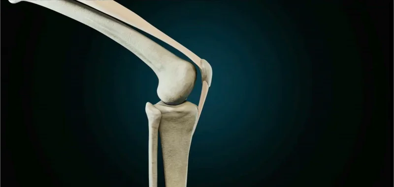
As shown in Fig. 4, knee torque demand is highest when a human stands up from a seated position, which corresponds to a deeply flexed knee angle.
Designing a robot knee that loses torque near full flexion leads to:
- Increased power consumption
- Control instability
- Structural vibrations
- Reduced actuator lifespan
This issue can be observed in robots such as Apptronik’s Apollo, which employs a conventional slider–crank mechanism in its knee and elbow joints (Fig. 2).
Earlier Solutions: Hoeken’s (Chebyshev Lambda) Linkage
To address this problem, engineers working on the DARPA-funded THOR humanoid robot introduced an inverted Hoeken’s linkage around 2015 for its Hip and Knee joint.


As illustrated in Fig. 6, Hoeken’s linkage (red curve) delivers a nearly constant torque profile across a useful range of motion when compared to a conventional slider–crank (blue curve).
The physical implementation of both mechanisms is shown in Fig. 7, where the improved torque behavior is clearly evident.
The Packaging Problem

Despite its favorable torque characteristics, Hoeken’s linkage introduced a new issue of poor packaging.
The extended link (highlighted in yellow in Fig. 5) caused the actuator assembly to protrude outside the leg envelope.
This drawback is clearly visible in Fig. 8, which shows the hip and knee assembly of the THOR robot. While mechanically effective, the design was unsuitable for compact humanoid robots.
Tesla’s Breakthrough: A Modified Hoeken’s Mechanism
Instead of abandoning the concept, Tesla refined it.

Optimus develops a compact, modified Inverse Hoeken’s linkage, inspired directly by human knee anatomy. The human knee itself is not a simple hinge, it behaves as a biological four-bar linkage, balancing torque throughout its range of motion.
This biological principle is captured as a mechanical analogue in Fig. 9, where Tesla replicates the knee’s natural kinematic behavior using a compact linkage geometry.
Final Outcome

The final implementation, shown in Fig. 10, achieves:
- Near-constant torque delivery across the knee’s range of motion
- High torque availability at deep flexion
- Compact packaging suitable for humanoid legs
- Reduced distal mass and lower mass moment of inertia

All of this is achieved while maintaining mechanical simplicity and energy efficiency.
Closing Thought
Tesla’s Optimus does not move away from QDDs because they are flawed, but because they are not optimal for high-load, limited-rotation joints such as the knee and hip. In these joints, factors like torque density, inertia management, and energy efficiency outweigh the advantages offered by rotary actuation.
Beyond their primary role in actuation, Tesla has also integrated linear actuators as structural members within the robot’s upper limb, allowing them to serve a dual-purpose delivering motion while simultaneously contributing to load-bearing and structural stiffness.
Tesla has filed patents covering this design for its own implementation. However, this does not prevent other manufacturers from exploring similar architectural principles, and it is likely that we will see new interpretations of this approach emerge in the near future.
If one wonders why companies like Boston Dynamics or other manufacturers have not adopted this exact configuration, the answer lies in design philosophy. Their robots are largely inspired by human biomechanics, with modifications aimed at enhancing performance within that paradigm. Tesla, on the other hand, appears to be less constrained by biological imitation and more focused on first-principles, system-level optimization.
By combining:
- Linear actuators
- Modified four-bar kinematics
- Biomechanics-inspired geometry
- Actuators also as a structural member
Tesla demonstrates a critical lesson in robotics:
Performance is not dictated by actuator choice alone, but by how force, inertia, and geometry interact across the entire mechanism.
Sometimes, the smartest innovation is not inventing something new but engineering physics the way nature already has.
Bibliography
- Miskovetz, L., Bolsens, B., Huang, E., Herrmann, S., Han, J., & Inc, T. (2022). WO2024072984A1 – Actuator and Actuator Design Methodology – Google Patents. https://patents.google.com/patent/WO2024072984A1/en ↩︎
- Apollo. (n.d.). https://apptronik.com/apollo ↩︎
- Wikipedia contributors. (2024, December 9). Chebyshev lambda linkage. Wikipedia. https://en.wikipedia.org/wiki/Chebyshev_lambda_linkage# ↩︎
- Knabe, C. S., Orekhov, V., Hopkins, M. A., Lattimer, B. Y., & Hong, D. W. (2014). Two configurations of series elastic actuators for linearly actuated humanoid robots with large range of motion. IEEE-RAS International Conference on Humanoid Robots (Humanoids), 1096. https://doi.org/10.1109/humanoids.2014.7041503 ↩︎
- Knabe, C., Lee, B., & Hong, D. (2014). An inverted straight line mechanism for augmenting joint range of motion in a humanoid robot. International Design Engineering Technical Conferences & Computers and Information in Engineering Conference. https://doi.org/10.1115/detc2014-35123 ↩︎
- Jafari, R., & Inc, T. (2022b). WO2024073135A1 – Systems and Methods for a Robot knee Joint assembly – Google Patents. https://patents.google.com/patent/WO2024073135A1/en ↩︎
- Tesla. (2022, October 1). Tesla AI Day 2022 [Video]. YouTube. https://www.youtube.com/watch?v=ODSJsviD_SU ↩︎

Leave a Reply